Week 06 - Electronics & Open Design
15.03.19
Problems encountered & solutions found
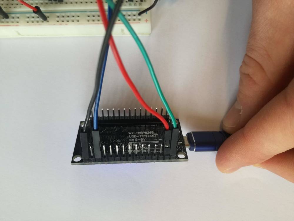
We actually began with different components, the vibration sensor and the solenoid component. We then made a circuit with just the vibration sensor but the wasn’t able of uploading the code. It said “error: espcomm_upload_mem failed” and even Kaj wasn’t able of changing it. What worked was restarting the computer and replacing the NodeMCU 0.9 (ESP-12 Module) which we also found out was dead.
Then we tested the vibration sensors with code found on the web but found out a cord on the vibration sensor was broken which could explain why that one didn’t work. We then tried another one but didn’t measure any respons which made us replace it with the tilt component that then did work with the same code.
We had an LED attached as well to see if it would react to the vibration sensor/tilt sensor. When this one worked we simply changed it with to the vibration motor without further tweaks. We then changed the “HIGH/LOW” settings to the opposite so the vibration motor would be on when the tilt sensor was activated.
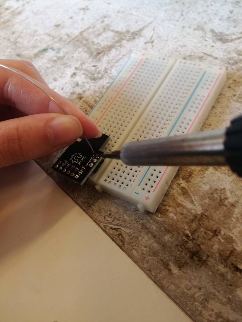
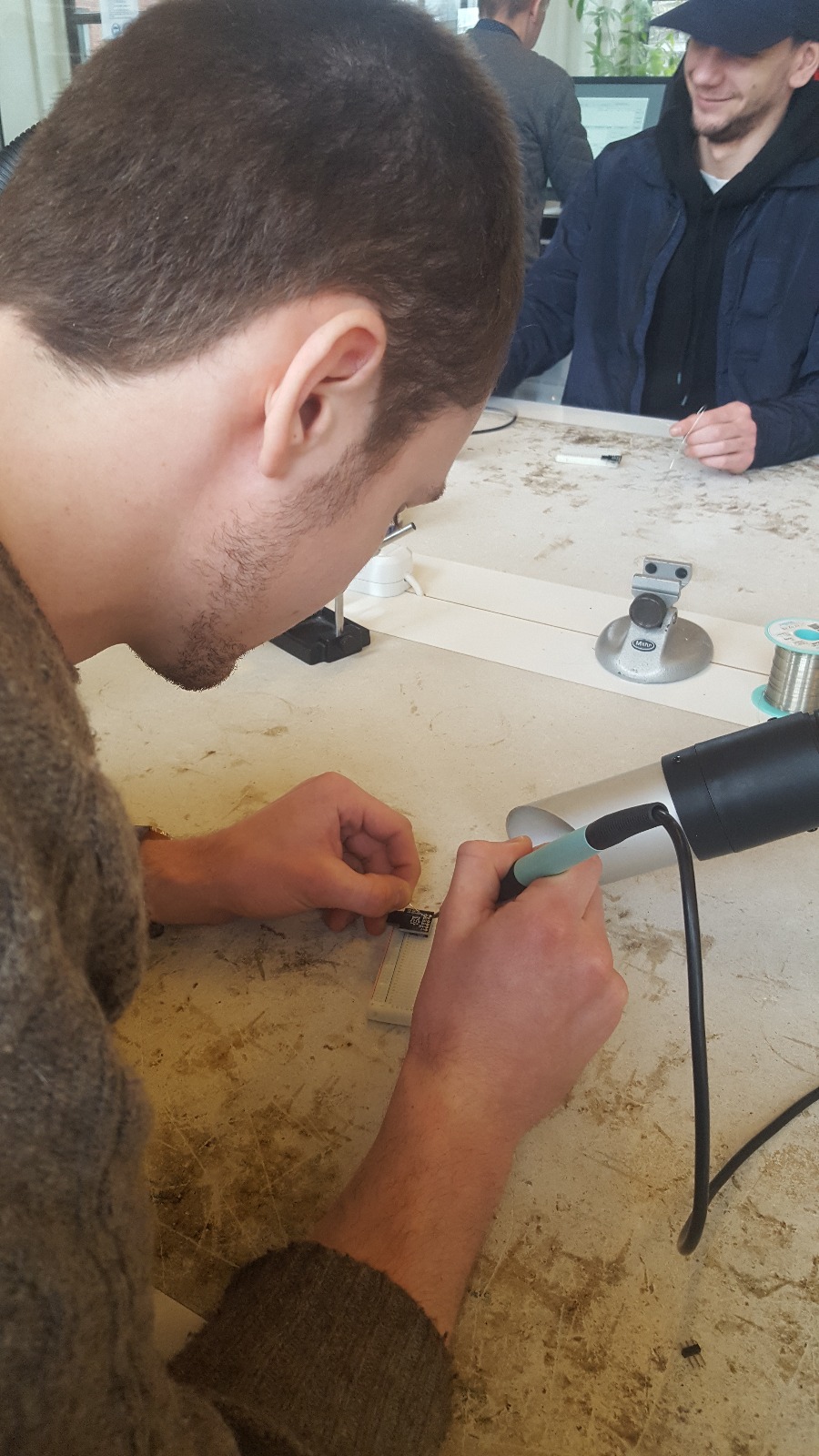
To solder or not to solder
First task in the electronic & open design week was to solder the "legs" to a small PCB. Unfortunately, this board wasn't fit for the following tasks, but it allowed us to have a little practice with soldering.
I have done a slight bit of soldering before years ago, but I'm lacking the patience to heart up the workpiece enough for the soldered tin to be "shiny" which a good soldering is supposed to be for having the most strength.
..was however a bit different: To explain the use of two different components. One sensor and one actuator. We actually got an extra actuater as you will reckon. The follewing is therefore a manual for using using a PCB board with a tilt sensor, a vibrate motor and a standard servo.
The main task.
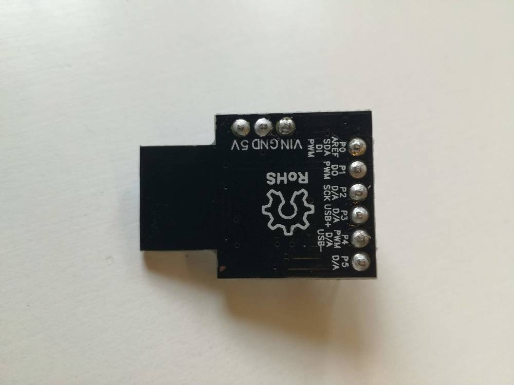
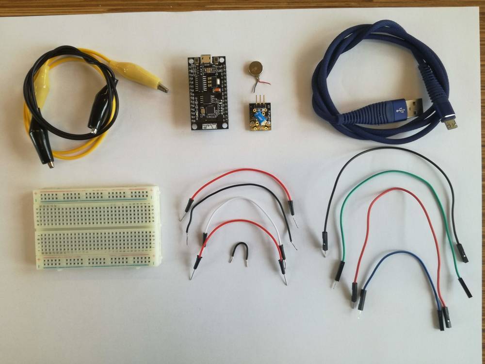
1) Find the required components
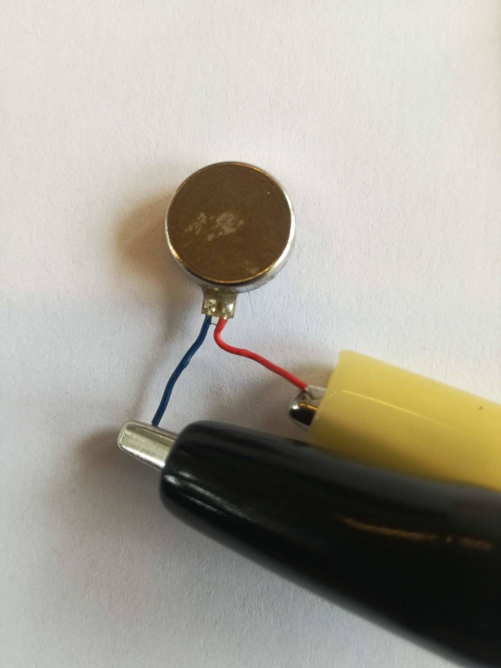
UPS. It's not necessary to use the same amount of cords that are showed un the picture. We e.g. used the crocodile clips only because they were easier to attach to the small cords from the vibrator motor.
Special components
10mm Vibration Motor - 3mm Type. Model 310-101
An actuator that vibrates on/off. Different voltage gives different fluctuations though. To be bought at (click link below):
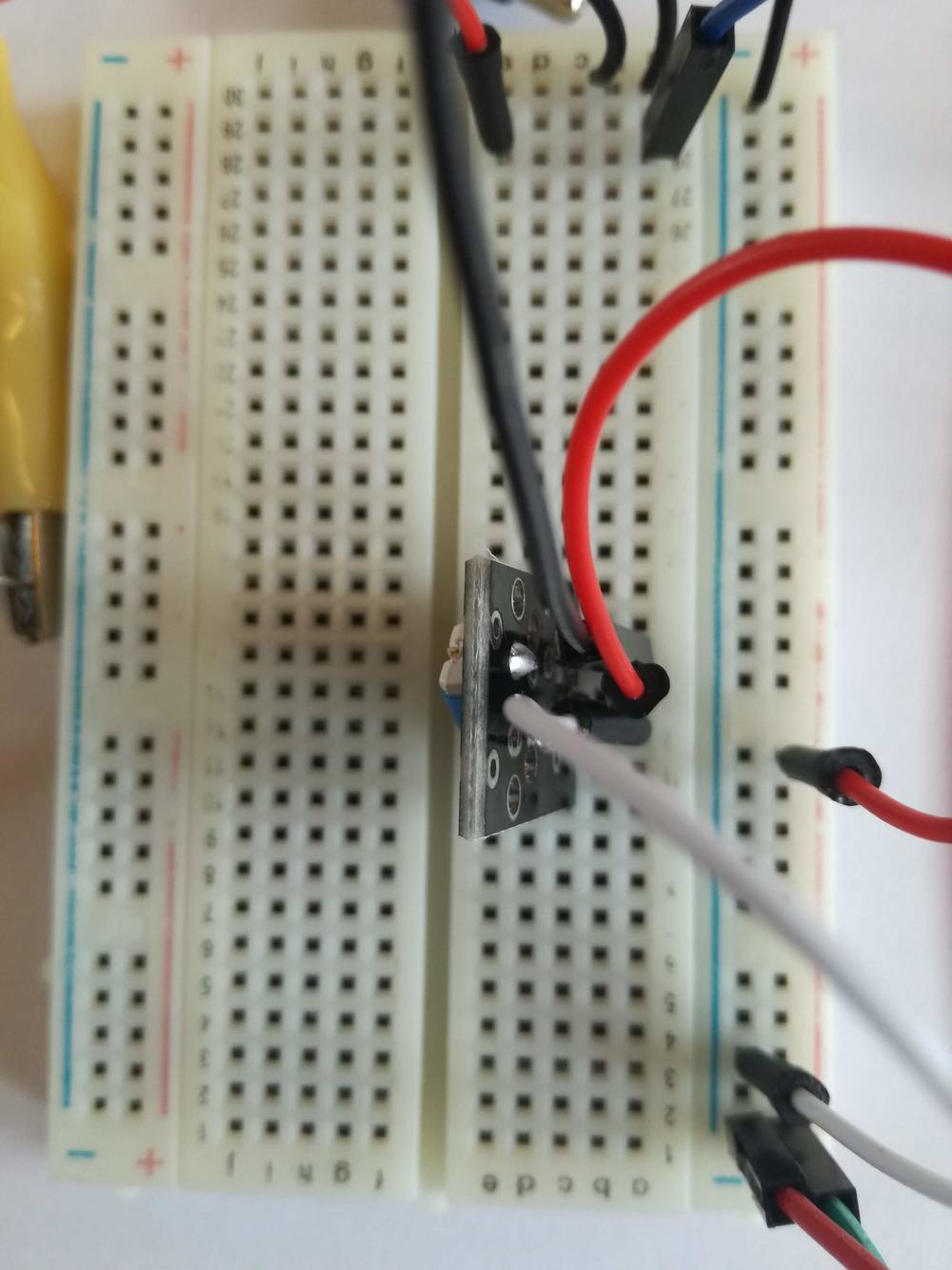
KY-020 tilt sensor
A sensor that reacts like a switch when tilted. Works by a ball inside creates a curcuit when it touches specific sides of the 'box' it's stored in. Click link below for shop
https://www.hobbyelectronica.nl
Link for datasheet below:
Vibrator motor datasheet
https://www.ebay.com
Link for datasheet below:
Tilt sensor datasheet
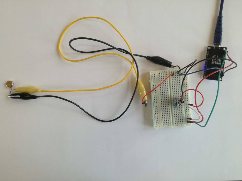
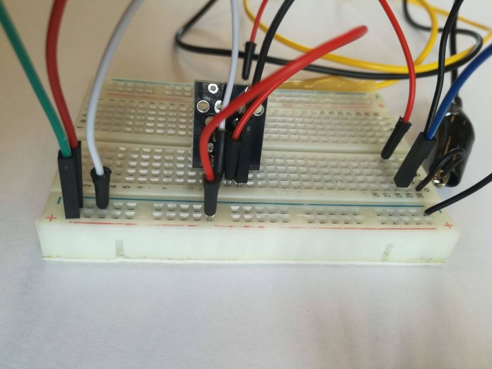
2) Assemble components according to pictures below
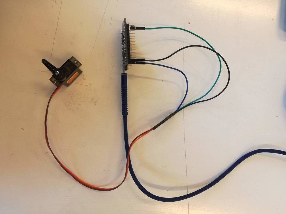
Overview of how the circuit can look like
'Fritzing drawing' of the circuit
2,1) Assemble components
Assemble the curcuit due to the fritzen drawing on the left. The 'overview' picture will seem more complicated due to the not so efficient use of cords AND you would have to take into account that the tilt sensor is stuck into the breadboard 'mirrored' compared to the fritzing drawing.
Scematic drawing of the circuit
3) Bring in that code!
Ctrl c -> Ctrl v. I know you can do it!
How it's supposed to look like below..
Click here for link to code
4) But why coffee - and is it really ready to serve?
We imagined both the tilt sensor and the vibration motor to be used on professional barista milk jugs. It’s hard to get out the last bit of milk foam, but with the vibrator starting when you tilt the jug, the vibrations will ‘loosen’ the last bit of milk foam minimizing the waste.
There are more normal uses for these componets though.. The vibration motor is found in mobile phones to make them vibrate when a text or an incoming call is received. The tilt sensor can be found in bilge pumps that are used in e.g. wooden boats or flooted basements making them pump when the water rises etc.
5) Ohh, but we have an extra feature for you! THE SERVO
Mr. RC M-1502 Standard Servo
An actuator with a rotating arm
https://www.rcmoment.com
6) ..With a little code
How it is supposed to look like
Basic code + tips 'n' tricks provided by:
Credit: The code used is originaly made for the KY-002 Vibration Sensor taken from: https://rydepier.wordpress.com/2015/10/08/vibration-sensor-ky-002-with-arduino/
In addition we changed the the settings for HIGH/LOW so the that it would vibrate when tilted instead of vibrating constantly until tilted.
https://www.arduino.cc/en/tutorial/sweep
Our modified code:
https://github.com/AsleLundorff/Servo-1/blob/master/Servo
7)Feedback given
Basic code + tips 'n' tricks provided by:
Be aware that the drawing has a mistake! Instead of D2 the yellow cord should be attached to D1!!
Feedback to Elisa for infared obstacle sensor:
- Make an original and complete fritzing drawing AND a schematic drawing. It's quite confusing with only the one present and the GIF pt. and it would give a nice overview.
Unclassified notes
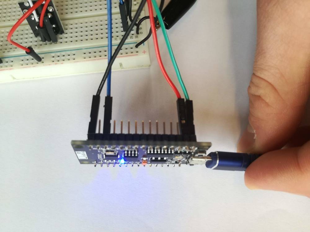
- Together with Elisa we were at the beginning only capable of making the sensor work. We tried to go everything through but what worked was removing the resistor. We also tried changing it to a new one of the exact same kind as they used, but that didn't work either.
Video of the working circuit. The LED shines very bright since there is no resistor. One could have tried different resistors and measured the OHM/eventual lack of closed curcuit with voltmeter
Feedback to Neza regarding the Neopixel Matrix
- Go through the 'fritzen' drawing again and make up the small mistakes with the cords
- Change order of the manual for logic chronology:
1) Fritzen drawing/create circuit
2) Libraries needed + code
3) How to change the code/functions of the neopixel matrix
Unclassefied notes
- The lousy PCB-boards gave quite some struggle. They got VERY warm and one was ruined..
- Read the instructions carefully and DON'T plug in the PCB board without having installed the required library
8)Feedback given
8)Collaborative Learnings
Working with Rick De Vos showed how it's possible to face a task in very different ways.
Rick had already some experience with PCB boards, making circuits and coding. Therefore, he didn't need to understand everything "from scratch" meaning, that when he saw a manual for a circuit on the web, he tried to copy it 100% onto the breadboard and copy paste in the code - because it's more efficient. He did already understand the principles and didn't need to involve himselfe understanding the specific circuit in a technical way. I, on the other hand, hadn't tried to use a breadboard before and therefore I went to the task less intuative but more deductive. I thought of the flow of electricity as water trying to make sense of it.
9) The feedback recieved from Elisa & Neza
The conclusions from the feedback I was given were:
- Write more about what the specific actuator or sensor does
- Find data sheet for the servo
- (probably have forgotten something.. Elisa nor Neza have mentioned it on their pages yet though)
